
PHYSICS AND THE VISUAL ARTS
Notes on LAB 9
THE CAMERA
Activity 1: Part 2.
Figure 1 shows a camera similar to the one provided in your kit. Turn the camera all around and examine how the case is held in place.
You will need to peel back the yellow paper to reveal the clips on the top and bottom that hold the back and front together.
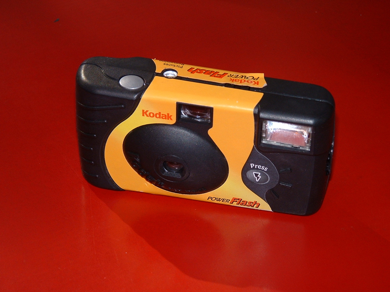
Fig. 1. Front view of a single-use camera.
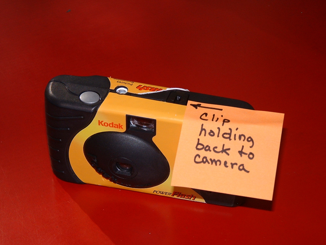
Fig. 2. Front view of camera showing paper removed to reveal to clip.
You will also need to release the clips on either end of the camera if you have
not already done so. They are in the center of each end.
Although they are hard to see in Fig. 3, the arrow points to the location.
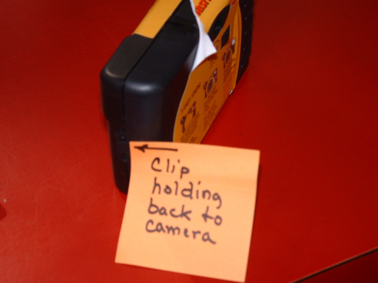
Fig. 3. End view of a single-use camera.
Be sure at this time to leave the front of the camera in place as you remove the back. In Fig. 4 you can see the sprocket wheel just
above the opening that leads to the shutter. The sprocket wheel's color varies from camera to camera. Most are gray or blue, but some are
even black. Just above and to the right of the sprocket is the gray thumbwheel used to advance the film and a white wheel with numbers
to designate the remaining unexposed frames. When film was in the camera, turning the thumbwheel pulled the film across, turning the sprocket
wheel until the shutter is cocked.
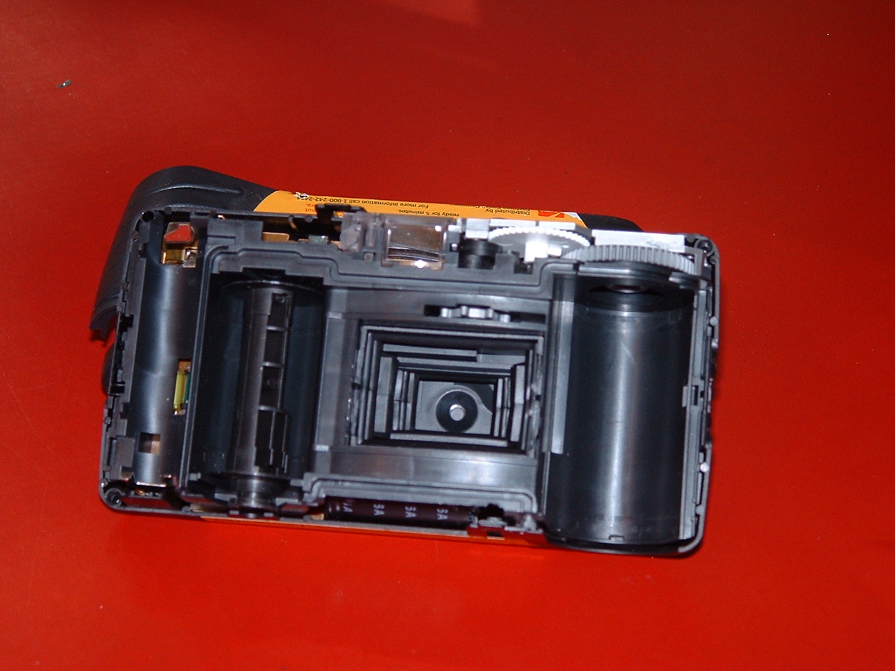
Fig. 4. Inside view of a single-use camera with the back removed.
Activity 2: Part 1.
Insert a AA battery into the battery holder with the positive terminal toward the bottom as shown in Fig. 5.
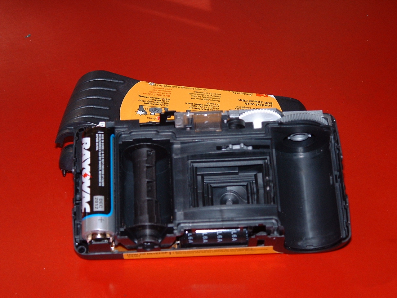
Fig. 5. Single-use camera showing position of AA battery.
Activity 2: Part 3.
In order to remove the front of the camera case, you will need to pull outward on each end to release the catches.
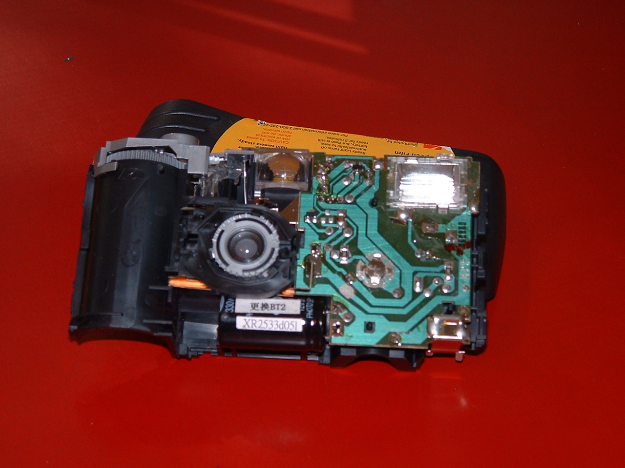
Fig. 6. Front view of camera. The capacitor is seen at the bottom
center of the front.
It has two white labels on it. The
contacts (electrodes) to the green circuit board are
immediately to the right of the capacitor.
Activity 5: Part 1.
The lens retaining ring can be seen in Fig. 6. You can rotate it counterclockwise to free the lens.
Activity 5: Part 2.
Replace the lens back into is mount and fix it in place with the retaining ring. Then remove the entire lens mount. Use a knife or nail
file to pry loose the left side of the lens mount. Figure 7 shows the lens mount removed. Notice the little piece on the bottom
left that held the mount in place. That is the piece you need to loosen in order to remove the mount. With the shutter moved aside you
can see and measure the aperture that limits the amount of light admitted.
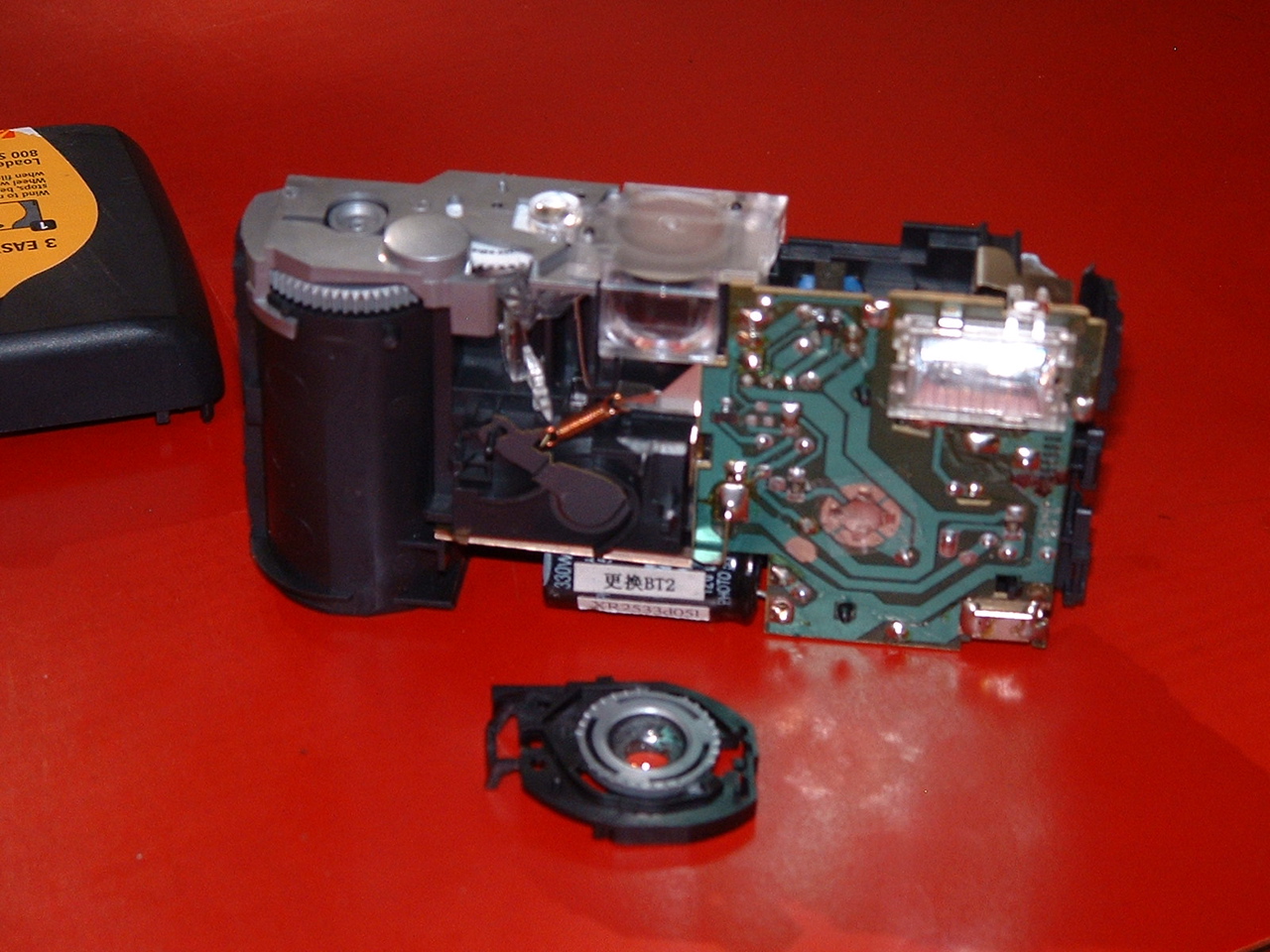
Fig. 7. Single-use camera with lens mount removed. Notice that
the shutter is
revealed along with the mechanism that
moves it and the spring that pulls it back.
Back to Physics 153 Home.
Back to Physics Dept web page.
Back to USC home page.
Last Modified: 07/14/11
Maintained by:rjones@mail.psc.sc.edu